

In Part 2 we saw how twisting a wire pair cancels interference at the source. But some noise still rides along a finished cable as common-mode current. Suppressing it is the job of a ferrite: a small magnetic part you slip over a cable so it absorbs the noise and dissipates it as heat.
This third article looks at ferrite beads and cores then walks through how to choose and size one for a real cable.
Key takeaways:
- A ferrite bead (or core) is a ceramic magnetic component that slips over a cable to suppress high-frequency EMI and common-mode noise.
- A ferrite behaves differently at every frequency, so its impedance-vs-frequency curve decides whether it will work in your band.
- Winding a cable through a toroid raises impedance fast
What Is a Ferrite Bead? Ferrites on Cables Explained
A ferrite bead — also called a ferrite core or choke — is a magnetic part that slips or clamps onto a cable to soak up high-frequency electromagnetic interference (EMI). Ferrites are ceramic materials (made of iron oxide + a mix of manganese or nickel with zinc) that have unique magnetic properties that are used to suppress Electro-Magnetic Interference (EMI) and Electro-Magnetic Compatibility (EMC) in circuits. The ferrite ceramic can be formed into different shapes such as plates, cylindrical tubes, and circular toroids to fit a specific application.
We will be looking at cylindrical tubes and circular toroids as a way of reducing noise on cables.
How Do Ferrite Cores Reduce Noise?
A ferrite doesn't reflect or block noise the way a metal enclosure does. Instead, it presents a frequency-dependent impedance to the cable: in the band it's designed for, it looks like a large resistance that converts the unwanted high-frequency current into a trace of heat, while leaving the wanted lower-frequency signal almost untouched. Because that impedance builds on the magnetic field around the wire, ferrites are especially good at killing common-mode noise, which is the interference present on every conductor of a cable at once.
Ferrite Impedance vs Frequency
A ferrite's impedance is not a single value. It rises and falls with frequency, which is why the datasheet is the starting point for any design. The ferrite data sheet needs to be used the obtain the appropriate operating parameters at the desired frequencies that needs to be controlled.
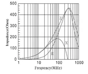
Ferrites are designed to work on specific frequency bands, so that the datasheet is an important tool to use before installing in a circuit. Additionally, the ferrite has a saturation magnetization that depends on the current and temperature that can reduces the impedance (Z).
How Many Turns? Winding and Stacking Ferrites
There are two ways to squeeze more attenuation out of ferrites: wind the cable through the core more times, or place several cores in a row along the cable. They don't scale the same way.
Winding: More Turns Through the Core
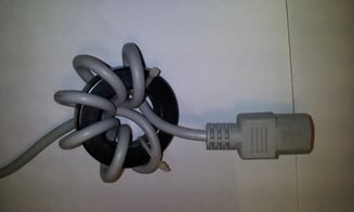
Passing a wire through the ferrite inner core will increase the attenuation (impedance (Z), resistance (R), and reactance (X)).
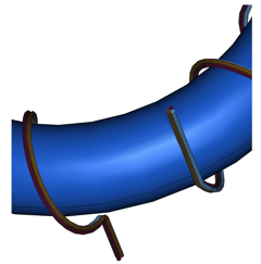
By convention, toroid turns are counted as the number of wires going through the center of the core, wires on the outside are not counted.
The inductance increase is proportional to the square of the turns of wire in the core.
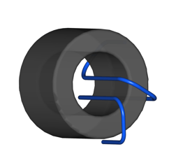
The ferrite core with two turns (N=2) will have four times (N2 = 4) the inductance of a comparable core with only one turn of wire.
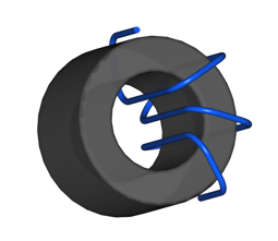
The three-turn (N=3) ferrite core will have nine times (N2 = 9) the inductance of the one wire case.
Wire bundles in cables can also be used with ferrites to eliminate common mode signals.
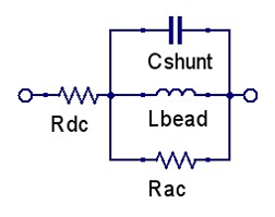
An equivalent circuit that can be derived from the impedance vs frequency plot.
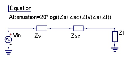
With the operating point impedance determined, we can calculate an attenuation of an interfering signal (Vin) that the load (Zl) will experience.
 |
 |
|
Simplified Equivalent Circuit |
Impedance to Attenuation |
Stacking: Ferrites in Series
The attenuation can also be increased by stringing the ferrites in series when the cable size does not allow for multiple loops. The effect of increasing in the number of ferrite core is additive, while at the same time lowering the overall frequency bandwidth.
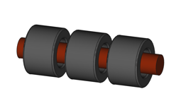
The increase of the inductance is linear; one turn = L, two turns = 2*L, and three turns = 3*L
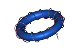
The wire bundles can be treated the same way as single wires, common mode noise which is present on all lines simultaneous can be reduced using the circular toroid.
In short: wind when you have room to loop, since the square law works in your favor; stack in series when the cable is simply too thick to wind.
Worked Example: Hitting a Target Attenuation in dB
We measure that an Ethernet cable has some noise at 60 MHz, and we would like to attenuate by 12dB. From data sheets or measurements, we find that the Ethernet cable has an impedance of 300 ohms at the desired frequency. Using the sample graph shown above, the impedance (Z) of the ferrite is 240 ohms at 60 MHz.
Re-arranging the attenuation conversion equation and solving for Zsc gives:

The source (Zs) and load (Zl) impedance are set equal for maximum power transfer (by design), to give:


The ferrite impedance (Zsc) and the load (Zl) impedance form a voltage divider that attenuates the undesired signal. The ferrite impedance needs to be increased by either passing the ethernet cable through the ferrite core multiple times or adding ferrites in series along the cable. In the linear case (ferrites in series) at least 7 to 8 ferrites are required to achieve the desired impedance (7*240 ohms = 1680 ohms: 11.59dB, or 8*240 ohms = 1920 ohms: 12.46dB).
When the Ethernet cable can be wound through a circular toroid, only 3 turns are required to achieve the desired attenuation (N =32 *240 = 2160 ohms:13.25 dB), with the advantage of only using one part.
 |
|
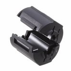
KEMET ESD-SR-100 Split Ring Ferrite |
Clip-On, Snap-On and Split Ring Ferrites
Everything above assumes you design the ferrite in from the start. Often you can't. That's what a clip-on split ring ferrite is for.
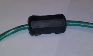
A split ring ferrite can be installed after a cable assembly is found to be causing EMI or EMC.
The split ring core needs to be properly clamped together when it is used in order to ensure the ferrite magnetization is not reduced due to the air gap between the two sections of the ferrite.
In practice, large circular toroids are available for cables with bulky adapters and connectors, the coil's inner diameter is large enough to allow the ends of the cable to pass through the inner ring. Flat ribbon cables can also be wound inside the toroid to improve RF shielding performance.
Put Your Design to the Test
Adding a ferrite takes seconds; proving it actually brought the emission down means measuring the cable before and after, with the right field probes and pre-compliance setup.
Averna designs and integrates RF test platforms across the full product lifecycle, from early prototyping through to high-throughput production. Explore our radio frequency testing expertise or get in touch with our RF experts.
You may also be interested in…

Read about the potential restraints and the strategies to conquer common RF test challenges in this free eBook!
Get in touch with our experts or navigate through our resource center.


