😮 With FREE Unbalanced Twisted Pair Calculator

The layout of conductors, components, and enclosures can interact to cause EMI and EMC problems. Catching the problem as early as possible with the use of design tools that estimate the spacing, routing, and adding well defined ground planes to a cable routing will greatly reduce the risk of EMI and EMC problems.
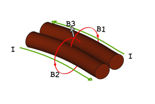 |
| Residual Magnetic Field from Parallel Wires |
A low-cost way of reducing E&M interference and compatibility is to twist wire pair together. Wires carrying current (I) in opposite directions generate separate magnetic fields (B1 and B2) that line up and create a residual magnetic field (B3). Using the right-hand rule with the thumb pointing in the direction of current flow the magnetic fields line up between the two wires shows the direction of the magnetic fields. The residual magnetic field can create crosstalk coupling between the wires and degrade external signals.
Twisting the wires together makes the residual magnetic field alternate around the length of the wires and confines it close to the pair. Nearby wires have much less crosstalk pickup since along the wire there are equal and opposite magnetic field spaced continuously every half turn that cancel each other out at a short distance.
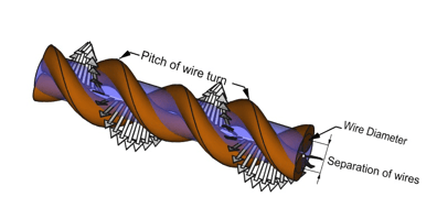 |
| Magnetic and Electric Field around a Twisted Pair |
The electric field (shown in blue) is also confined close to the twisted pair. The electric field sets up opposite charges on the surface of each wire and increase the overall twisted pair capacitance.
The twisted pair configuration adds additional inductance due to the magnetic field in the wire opposing the current flow.
The twisting (pitch) and separation of the wires can be used to set limits on signal bandwidth, spacing, and attenuation when twisted pairs are incorporated in a system.
Download this Unbalanced Twisted Pair Calculator to determine the equivalent Capacitance, Inductance, and Impedance of an unbalanced twisted pair.
For any questions on RF testing, please contact Averna.
--
By Peter Barabas
Senior Test Specialist - Engineering & Consulting
![]()
You may also be interested in…
Looking for more tips for better test? Download this eBook for inspiration!.
Get in touch with our experts or navigate through our resource center.