
While headlamps may seem like a straightforward part of a car, there are many considerations that need to be made before getting them to market. Each module and fully assembled lamp demands rigorous testing to ensure both safety and performance.
Key Takeaways:
- Headlamp testing is an end-of-line test that qualifies each lamp or module against its optical and functional specifications before it reaches the automaker.
- Photometry is the core measurement. A line either reads the beam relatively, against a known-good reference, or absolutely, in calibrated candela and lux that map to regulatory limits.
- A photometric vision station works as a loop: the lamp projects into a light-tight box, a calibrated camera captures the beam, and the software returns a pass or fail against the reference.
What is Headlamp Testing?
Headlamp testing is the end-of-line (EOL) test that confirms a headlamp or lighting module meets specification before it is shipped to the automaker. On every unit, it answers a specific set of questions:
- Does the beam land where it should?
- Is the luminous intensity within spec?
- Is the cutoff line sharp enough?
- Are the LEDs correctly positioned?
- Is the color within tolerance?
- Do the motors, solenoids, and adaptive systems behave as designed?
Different Ways to Test
A headlamp beam can be measured in more than one way, and it is worth knowing the options before looking at one station in detail. 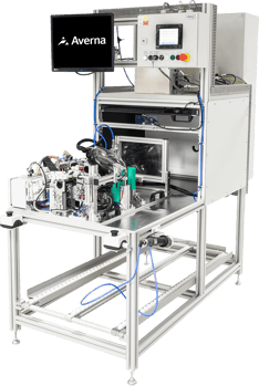
The reference method is goniophotometry: the lamp sits on a motorized stage that rotates and tilts in front of a fixed photometer, usually at 25 meters in a darkened tunnel, sampling the beam one angle at a time. It is highly accurate and underpins type-approval labs, but it is slow and needs a long light channel.
A second approach projects the beam onto a calibrated screen and reads the illuminance pattern off that surface.
The third, built for the factory rather than the lab, replaces point-by-point scanning with a calibrated camera that captures the whole beam pattern in one shot.
That speed is what makes imaging photometry the practical choice at the end of a high-volume line, and it is the technique this article follows.
It is also the one we know best, since we build our headlamp test systems around it, so the rest of this article will take place directly from the test floor!
How does a Photometric Vision System Test a Headlamp?
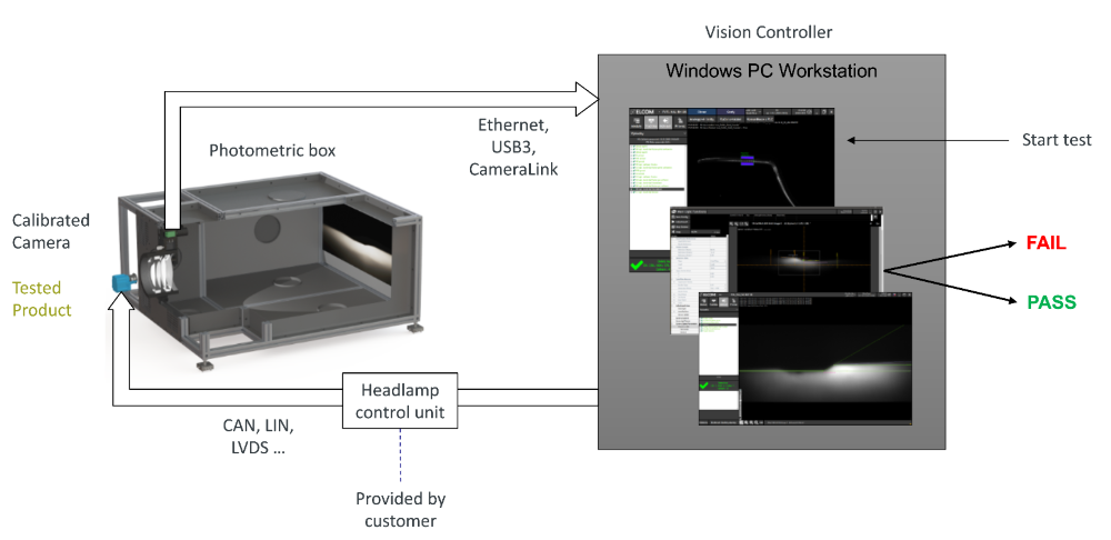
On the line, a finished lamp or module is placed in a vision inspection system, and then it’s a loop between optics and software. The lamp projects its beam into a light-tight enclosure called the photometric box, built to hold the geometry between the lamp and the sensor constant.
A calibrated camera captures the beam image and passes it to a vision controller over a high-bandwidth link such as Ethernet, USB3, or CameraLink.
The lamp is driven through its own control unit over automotive buses like CAN, LIN, or LVDS, so the system can command each function and light state during the sequence. Photometric software then compares the captured image against the reference specification and returns a verdict of pass or fail.
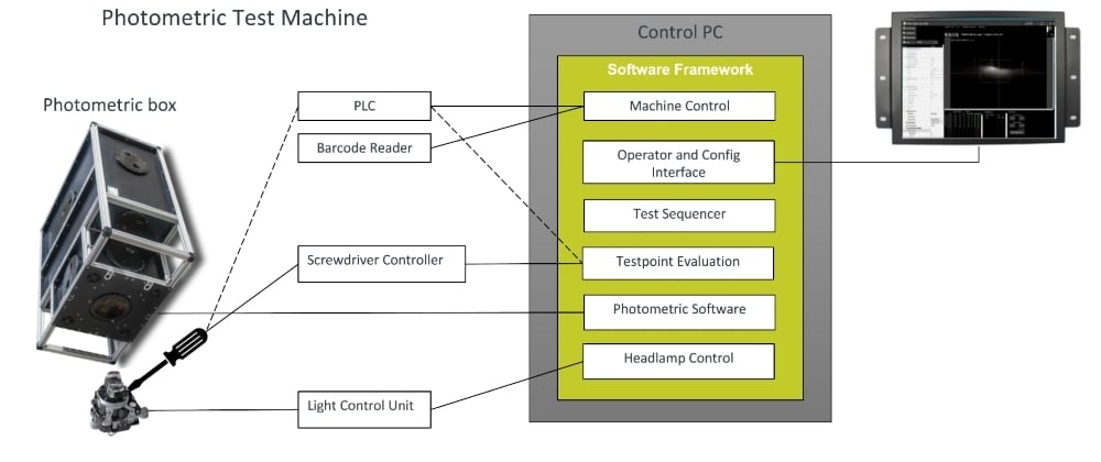
The station is also a set of coordinated subsystems under one software framework. Machine control, the test sequencer, testpoint evaluation, and the photometric software run alongside the shop-floor plumbing: a PLC, a barcode reader that binds each result to a serial number, and a screwdriver controller that drives motorized adjustment when the beam needs correcting.
Photometry at the Heart of Headlamp Test Systems
Photometry is the measurement of a beam's luminous characteristics: how much light reaches a given point, how that light is spread across the pattern, and what color it carries.
In a headlamp test system it is the core discipline, because almost every question that decides pass or fail resolves to a photometric quantity read off the beam image.
The first architectural choice a line makes is whether those readings are relative or absolute.
Relative Photometry
Relative photometry is a comparative measurement. Each unit is checked against a reference sample, a known-good lamp, rather than against an absolute scale. The system reports relative intensity, luminous uniformity, relative color, and beam position, then flags any unit that drifts away from the reference.
Because it does not depend on a calibration traceable to physical units, it is fast and robust, which suits high-volume production where the goal is to catch a lamp that deviates from the batch rather than to certify an exact value.
Absolute Photometry
Absolute photometry is a calibrated measurement expressed in real photometric units. Instead of comparing a lamp to a reference part, the system reports intensity in candela, illuminance in lux, beam angle, absolute intensity, and cutoff-line sharpness against a fixed scale.
This is the more demanding approach, since the camera and the full measurement chain have to hold a traceable calibration, but it is also the one that lines up with regulation. Standards like FMVSS 108 express low-beam and high-beam requirements as luminous intensity in candela at defined test points, so a lamp's compliance ultimately comes down to an absolute-photometry question.
Relative or Absolute Photometry: How the Two Compare
| Critère | Relative Photometry | Absolute Photometry |
|---|---|---|
| Reference | Known-good sample | Traceable calibrated scale |
| Units | Relative values | Candela, lux |
| Typical Measurements | Relative intensity, uniformity, relative color, beam position | Absolute intensity, beam angle, cutoff sharpness |
| Application | High-volume consistency checks | Compliance-grade verification |
| Cost | No calibration chain to maintain | Calibration overhead, regulation-aligned |
What is the Cutoff Line, and Why Does it Matter so Much?
On a low beam, the light has to reach far enough for the driver to see, without spilling upward into the eyes of oncoming traffic. The boundary that manages that trade-off is the cutoff line: a sharp horizontal edge between the lit road and the dark zone above it. Under FMVSS 108 the cutoff is defined as a broadly horizontal aiming cue in the lower beam that marks the separation between areas of higher and lower luminance.
Most asymmetrical low-beam patterns hold a horizontal segment on the traffic side and rise on the shoulder side to light signs and the road edge. The elbow where those two segments meet is the kink point, and it serves as the anchor the system uses to reference position and aim.
A test station measures three things on that boundary: its position, its angle, and its sharpness. Sharpness is the gradient across the edge, how quickly luminance falls from lit to dark.
A cutoff that reads soft or displaced is usually a symptom. A blurred edge can point to a lens seated slightly off, an LED placed outside tolerance, or an optical defect in the reflector or projector. Type-approval standards like UNECE Regulation 112 include an instrumental verification of the cutoff rather than leaving it to a visual check.
A displaced cutoff often just means the lamp is aimed wrong, and some stations fix that on the spot.
How does Automatic Beam Adjustment Work?
Some test stations not only evaluate a lamp but also correct it. When a headlamp is designed with adjustment screws, the test system can close the loop between measurement and mechanical correction without an operator touching the part.
The sequence is straightforward:
- The calibrated camera captures the beam image.
- The software compares the measured aim against the target and calculates the offset.
- A screwdriver controller then drives a motorized screwdriver onto the adjustment screw and turns it by the computed amount.
- A fresh image confirms the correction landed inside tolerance, and the unit is released or flagged for another pass.
The full loop runs fast enough to fit inside a production cycle. But aim and optics are only half of the lamp.
What Gets Tested Beyond the Beam?
A modern headlamp is an electromechanical assembly with its own electronics. Photometry only covers the optical half. A full end-of-line sequence also confirms that the hardware behind the beam behaves.
On the electrical side, the station measures the current drawn by the light sources, the solenoids, and the stepper motors that drive leveling and adaptive functions, catching a shorted driver or a stalled motor before the lamp ships. On the communication side, it exercises the lamp over its automotive buses, CAN, LIN, and RS-232 among them, to verify that each function responds to the right command and reports the right state.
Quality and presence checks run in parallel through the same vision hardware: cosmetic defects, correct component presence, the coating on the headlamp cover, and color faults in the light guides. Adaptive systems get their own validation, from aiming and leveling systems to PWM-driven intelligent modules, where the test confirms the lamp responds correctly to the control signals that will later steer it on the road.
Vision-Based Photometric End-of-Line Testing for Automotive Lighting Systems
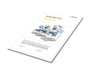 Everything in this article, from the photometric box and the calibrated camera to the pass/fail loop and automatic beam correction, comes together in a purpose-built production system. At Averna powered by Spherea, we design configurable photometric test platforms for automotive lighting that sit at the end of the line and scale from a single light source up to a complete multifunction lamp. Download the brochure by clicking on the image!
One station covers relative and absolute photometry and adds the electrical and communication tests a modern lamp assembly needs, with every result tied to its unit for traceability. Where a build calls for it, a feasibility study matches the configuration to the line before anything is committed.

You may also be interested in…
So many parts to a car, so little time! See how we designed a flexible inspection system for one of the world’s being truck manufacturers!


