Key Takeaways:
► An OCD Message equates to a Channel Map. It defines how the OFDM channel is structured, which helping modems decode it the right way.► Subcarriers have roles and are grouped by function like pilots, PLC, or excluded bands. This delivers an optimal performance.
► OFDM allows for flexible use of the spectrum. Operators can exclude selected parts to avoid noise or interference.
► A larger Discrete Fourier Transform (DFT) size means more subcarriers and higher control over the channel.
What is Orthogonal Frequency Division Multiplexing?
Version 3.1 of DOCSIS specifications, an international telecommunications standard for cable TV systems, introduces downstream Orthogonal Frequency Division Multiplexing (OFDM) channels, which are highly flexible in terms of frequency, bandwidth, modulation type, and active spectrum. This technology has changed telecommunications testing equipment forever.
How does Orthogonal Frequency Division Multiplexing work?
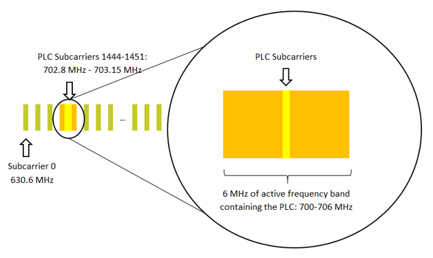
When a Cable Modem (CM) acquires an OFDM channel, the first step is to decode the Physical Link Channel (PLC), which is located in a 6 MHz active frequency range. The PLC has a specific structure, which allows the CM to easily decode its content without knowing all of the channel parameters.
The PLC carries critical information about the channel physical layer, such as the OFDM Channel Description (OCD) message, which is required by the CM to fully characterize the OFDM channel. The focus of this blog is on an OCD message that is extracted from a DOCSIS Protocol Analyzer. The message is analyzed in order to reconstruct the channel.
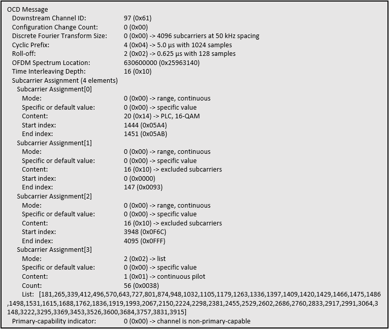
There are three parameters that will not be discussed: the Cyclic Prefix, the Roll-Off period, and the Time Interleaving Depth. These parameters are part of mechanisms used by the Cable Modem Termination System (CMTS) to reduce the effects of interference and maximize channel capacity. Rather, the focus here will be on the remaining parameters that define the OFDM channel in the frequency domain.
The Discrete Fourier Transform (DFT) Size in OFDM Channels

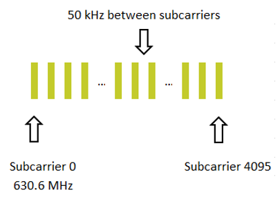
The Discrete Fourier Transform (DFT) Size indicates the number of subcarriers defining the OFDM channel in the frequency domain. In this case there is a channel defined over 4096 subcarriers.
The OFDM Spectrum Location

The OFDM spectrum location is the frequency (in Hz) of the lowest subcarrier (subcarrier 0).
Subcarriers in DOCSIS: Types and Assignments
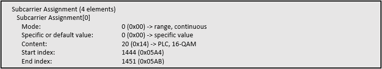
The Subcarrier Assignment section of the message is used to describe the nature of some subcarriers in the OFDM channel. The assignment will not change while the channel is included in the Receive Channel Set of a CM.
There are three possible subcarrier types assigned in the OCD: PLC subcarriers, excluded subcarriers, and continuous pilots.
Understanding OFDM PLC: What is PLC in OFDM?
The PLC subcarrier assignment defines which subcarriers are used to carry information on the PLC. There are 8 or 16 subcarriers allocated to the PLC, depending on the DFT size. These subcarriers are centered in a 6 MHz active frequency range.
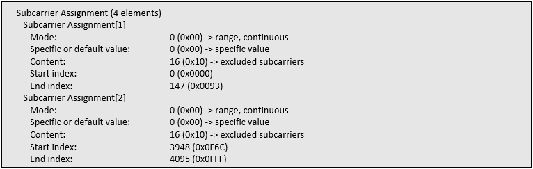
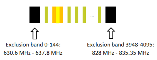
Excluded subcarriers cannot be used by this downstream channel for transmission. The CMTS can use the frequency covered by these subcarriers for transmission on other channels or as guard bands between channels. Exclusion bands can be located at different locations in the OFDM channel, allowing for greater flexibility while transitioning to DOCSIS 3.1 technology.
In this case, there are two different exclusion bands between subcarriers 0-147 and 3948-4095.
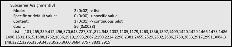
The CM uses continuous pilots in the OFDM channel as reference signals to facilitate synchronization. They do not convey data but are necessary for successful decoding. Continuous pilot subcarriers have twice the amplitude of other non-pilot subcarriers. The assignment includes the continuous pilots contained in the PLC band, which are expected at specific locations.
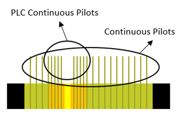
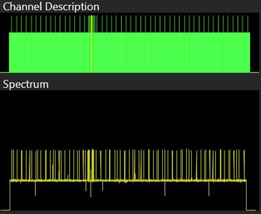
Visualizing DOCSIS Channels Explained
The DOCSIS Protocol Analyzer displays a visual representation of the OFDM channel description when locked on this kind of channel. An example for the same channel as described by the OCD message is displayed in the image below.
Why OFDM Analysis Matters
OFDM analysis in DOCSIS enables high-speed data transmission over cable by using spectrum most effectively. It breaks data into multiple subcarriers and improves resistance to interference and signal degradation, particularly in noisy environments. Analyzing OFDM performance allows operators to optimize modulation, identify impairments and ensure reliable service delivery. OFDM analysis is key to maintaining and enhancing quality in modern cable systems.
For more information about how the Jupiter 310 or our other DOCSIS test equipment, can help in RF testing and certification, design, network monitoring and debugging, contact Averna.