
Many modern conveniences we take for granted, like the "blue dot" on our smartphone maps or the precise synchronization of high-frequency trading floors, rests on Global Navigation Satellite Systems (GNSS).
We’ve become so dependent on this celestial infrastructure that its failure would trigger a massive crisis. When your position is off by 3 blocks, you are experiencing the friction between a multi-billion dollar satellite array and the reality of the physical world.
While we colloquially call this feature "GPS," that term only describes a single chapter of a much larger, high-stakes story of global sovereignty and physics.
Key Takeaways:
- GNSS is the overarching system. GPS is one member of it, alongside GLONASS, BeiDou, and Galileo.
- Multiple constellations exist for reasons of sovereignty and regional geometry.
- All of these systems crowd into a narrow band of L-band spectrum, with several sharing identical center frequencies.
- Field testing alone cannot separate a receiver's weaknesses from the environment's. A record and playback system can.
Meaning of Global of Navigation Satellite Systems
Global Navigation Satellite System, abbreviated to GNSS, refers to a constellation of satellites that broadcast timing and orbital data, allowing a receiver on the ground to compute its position. Any GNSS is built from three segments:
- The space segment is the satellites themselves, each carrying atomic clocks and broadcasting a navigation message.
- The control segment is the network of ground stations that tracks the satellites and uploads clock corrections.
- The user segment is every receiver that listens (a survey-grade antenna, a chipset in a smart watch, etc).
Generally, four satellites broadcast signals that are received by a GPS receiver. By measuring how long each signal takes to arrive, the receiver calculates its distance from each satellite. This process, known as trilateration, is used to determine the receiver's position. While three satellite distances are theoretically enough to determine latitude, longitude, and altitude, a fourth satellite is needed to correct the receiver's clock error and accurately compute its position.
How Many GNSS Constellations are There?
GPS has become the Kleenex of satellite navigation, a brand name that swallowed its own category. In practice there are four operational global constellations, and a modern receiver almost certainly uses more than one of them at once.
| System | Owner | Nominal constellation | Status |
|---|---|---|---|
| GPS | United States | 24 slots, 6 orbital planes | 31 operational satellites |
| GLONASS | Russia | 24 satellites | Operational, optimized for high latitudes |
| BeiDou (BDS-3) | China | 30 operational satellites | Global service since June 2020 |
| Galileo | European Union | 24 active plus spares | Constellation complete as designed since January 2025 |
The figure of 55 satellites turns up constantly for BeiDou, but that counts every satellite launched across three generations of the program rather than the constellation that is actually working today. BDS-3, the global system, runs on 30 operational satellites spread across medium Earth, geostationary, and inclined geosynchronous orbits. In March 2026 the China Satellite Navigation Office announced an in-orbit upgrade to improve signal accuracy and precise point positioning, with roughly 50 BeiDou satellites in orbit in total.
Alongside the global four sit two regional systems.
Quasi-Zenith Satellite System (QZSS)
Japan's QZSS, nicknamed Michibiki, has provided service since November 2018 and covers the Asia-Oceania region with a focus on Japan. Its satellites follow highly inclined geosynchronous orbits that keep at least one spacecraft near the zenith over the Japanese archipelago at all times. This is a direct answer to the problem of urban canyons and mountainous terrain.
QZSS began as a GPS augmentation rather than a replacement. That is changing. The Cabinet Office is expanding the system to seven satellites, which is the threshold at which four or more QZSS spacecraft are always visible over Japan and positioning becomes possible using QZSS alone. A revised national plan now points beyond that, toward an eleven-satellite constellation by the late 2030s.
Navigation with Indian Constellation (NavIC)
India's system, originally IRNSS and renamed NavIC in 2016, was designed around seven satellites covering India and a region extending roughly 1,500 km beyond its borders. In November 2020 the Maritime Safety Committee of the International Maritime Organization recognized it as part of the World Wide Radio Navigation System.
NavIC is also the clearest illustration of how fragile a constellation can be. A series of atomic clock failures has taken multiple satellites out of navigation service, and the NVS-02 replacement launched in 2025 failed to reach its intended orbit. Reporting indicates only a handful of NavIC satellites are currently capable of providing full positioning, navigation, and timing service.
Are All These GNSS Really Necessary?
Yes, for three reasons, and they’re all very important.
The first one is sovereignty. Satellite navigation is a fundamental tool of modern warfare and economic stability. UAVs rely on GNSS, for example. No government wants its military capability to depend on a foreign system that could be degraded or denied during a conflict. India's program is explicit on this point, and the same logic drives Beijing, Moscow, and Brussels.
The second is geometry. Satellites perform differently depending on their orbital altitude and inclination. GLONASS orbits at a higher inclination than GPS, which gives it better visibility at high latitudes. QZSS uses quasi-zenith orbits precisely because a satellite low on the horizon is useless in a Tokyo street lined with towers. A system tuned to a specific region will outperform a global system in that region.
The third is that multi-constellation reception is simply better. A receiver that can track GPS, Galileo, GLONASS, and BeiDou together sees far more satellites, which improves geometry, shortens time to first fix (TTFF), and makes the position solution more robust.
What is the GNSS Spectrum?
Every one of these systems broadcasts in a narrow stretch of L-band, roughly 1164 to 1300 MHz and 1559 to 1610 MHz. That is not a lot of room for six independent programs. The result is a spectrum that is both crowded and deliberately shared.
GPS L1C, Galileo E1, and BeiDou B1C all sit on 1575.42 MHz. GPS L5, Galileo E5a, and BeiDou B2a all sit on 1176.45 MHz. Interoperability was negotiated between the United States, the European Union, and China so that a single receiver front end could capture several constellations at once, with the signals kept separable through different modulation schemes rather than different frequencies.
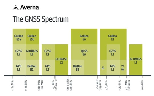
Some of it is not shared at all. GLONASS historically used frequency division multiple access, assigning each satellite its own channel around 1602 MHz, which is a fundamentally different architecture from the code division approach everyone else adopted. NavIC broadcasts on L5 but also in S-band at 2492.028 MHz, well outside the L-band cluster entirely.
Sharing a center frequency does not mean sharing a signal. Modulation, encoding, framing, encryption, and message structure differ from one constellation to the next. A receiver has to demodulate each one correctly, and a test system must be able to produce and capture each one correctly. This is why GNSS testing is harder than other types of RF testing: the spectrum is narrow enough that you can capture most of it in one shot, and heterogeneous enough that capturing it is only the beginning...
Which GNSS Receiver Tests Actually Matter?
There are different ways to perform GNSS receiver testing, and each one answers a different question.
GNSS Simulation
A simulator generates GNSS signals mathematically, from a model of satellite orbits, clock behaviour, and atmospheric delay. You define a trajectory, a date, a constellation mix, and the simulator produces the RF signal that a receiver would see under those conditions.
The strength of simulation is control. You can place a receiver in Reykjavik at midnight in a solar storm without leaving the lab, run the same scenario a thousand times, and get the same answer. You can push the receiver into corner cases that would take months to encounter in the field.
However, the limit is fidelity. A simulator produces the errors it was told to produce. It models the ionosphere, satellite clock drift, and orbital error well. It does not model the specific concrete facade on the corner of your test route, and it will not reproduce the scattered behavior that a tree canopy imposes on a signal.
Field Testing
Done properly, field testing has four components.
- It needs a reference system, typically a high-grade receiver coupled with an inertial unit, producing the truth trajectory against which everything else is judged. Without truth data, a drive test observes behaviour but measures nothing.
- It needs a route designed to break things, with bridges, urban canyons, short tunnels, tree-lined roads, and parking entrances, because each obstacle type produces its own error signature.
- It needs synchronized capture of the raw signal alongside the reference position and, ideally, contextual video, so that an anomaly in the position log can be traced back to the physical object that caused it.
- And it needs repetition, because a single pass under a bridge is a single sample of a chaotic environment.
What field testing cannot do on its own is isolate a cause. When a receiver reports a bad position under a bridge, the drive alone will not tell you whether the fault lies in the receiver, the antenna, the antenna's placement on the vehicle, or the bridge. Every variable moved at once, and it will never move the same way twice.
Record & Playback
Record & playback resolves that tension by capturing the RF environment once, at full fidelity, and replaying it in the lab as many times as needed. GNSS simulators are valuable, but they cannot fully reproduce the complexity of real-world RF environments. Several real-world conditions are difficult or impossible to recreate perfectly with simulation, such as:
- Urban canyon environments with severe multipath
- Indoor navigation scenarios
- Dynamic vehicle and aircraft applications
- Atmospheric effects such as ionospheric scintillation
- Limited satellite visibility
 Because the recording contains the actual signals that arrived at the antenna, including the reflections, the diffraction around obstacles, and the local interference, it preserves the messiness that a simulator cannot model. Because it is a file, it is perfectly repeatable. You can replay the same difficult intersection through five candidate receivers and compare them against each other, or replay it through the same receiver across firmware revisions and see exactly what your change did.
A device can be consistently wrong in the same way every time, which is a bias problem, or it can be randomly scattered across repeated measurements, which is a stability problem. Those two failures have entirely different root causes and entirely different fixes. Averaging a single drive test together hides both. Replaying the same environment repeatedly separates them.
Important Measurements and Associated Tests
Buying a well-regarded chipset does not give you a well-performing product. The signal arriving from orbit lands at roughly minus 130 dBm, which is weak enough that your own board can drown it. Poor RF shielding, or a regulator sitting too close to the antenna, can turn a receiver with excellent published numbers into a device that cannot hold a fix in an open field. The datasheet describes the chip. Your product is not the chip, which is why test specification validation belongs early in the program.
Several measurements characterize an integrated receiver.
| Measurement | What it tells you | Signal source |
|---|---|---|
| Time to first fix (TTFF) | How quickly the acquisition engine produces a valid fix from a cold, warm, or hot start | Either. A simulator controls what the receiver knows at reset. EN 16803-2 also includes TTFF in its replay procedures. |
| Re-acquisition time | How quickly it recovers a fix after a brief outage, such as a tunnel or an underpass. A receiver can post an excellent TTFF and still recover badly, and almost nobody tests for it | Both. A simulator scripts the outage to the millisecond. Playback gives you the actual tunnel. |
| Position accuracy | How far the reported position sits from truth, and how often | Both, for different reasons. A simulator gives you truth for free and lets you script global-error scenarios. Playback gives you the real environment, provided you captured truth data alongside the RF. |
| Velocity accuracy | How closely reported speed and heading track the reference. GNSS delivers position, velocity, and time, and driver assistance functions consume all three | Both. A field testing’s reference system supplies velocity truth alongside position truth. |
| Timing accuracy | How closely the receiver's 1PPS output tracks the reference | Simulator. EN 16803-2 explicitly leaves timing tests other than TTFF out of replay, on the grounds that they need no field data and run better on lab instruments. |
| Sensitivity | The power floor for acquiring a signal, and the lower floor for holding one | Simulator. You need controlled attenuation in known steps, which a recording cannot give you. |
| Carrier-to-noise density (C/N0) | The signal quality the receiver actually sees, satellite by satellite. It degrades before the position does and it points straight at antenna placement or board noise | Neither, strictly. C/N0 is logged continuously during every other test rather than run as a test of its own, and a drop with no change in the RF you fed the device means the problem is inside your product. |
| Behavior under impairment | How the device degrades when conditions turn bad | Depends on the impairment. Ionospheric disturbance and corrupted ephemeris are global errors, so simulation. Multipath, foliage, and ambient interference are local errors, so playback. |
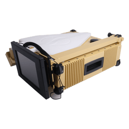 That last category deserves a note. Intentional interference, whether jamming that drowns the signal or spoofing that replaces it with a convincing fake, has moved from a theoretical concern to an operational one, particularly in aviation and maritime navigation. It is a large enough subject that it needs its own treatment. Teams running aerospace and defense test programs that need to verify behavior under deliberate interference today can look at Averna Powered by Spherea's field-deployable jammer verification system.
Beyond Accuracy: Can the Position be Trusted?
Accuracy tells you how close the receiver got. It says nothing about whether you should have believed it, and for anything safety-related the second question is very important.
Civil aviation settled this in the 1990s, building its Required Navigation Performance framework on different attributes: accuracy, availability, continuity, risk assessment and integrity. EN 16803-1 carries similar ones into road transport. Any receiver aimed at an autonomous or safety-critical function will be judged on them.
| Metric | The question it answers |
|---|---|
| Availability | What fraction of the time does the terminal deliver a position at all, in the environment it actually has to work in? |
| Continuity | Once it has a fix, how reliably does it hold one for the duration of the operation without dropping out? |
| Integrity | When the position is wrong, does the device know it, and does it say so? |
GNSS Testing with Averna
Validating a receiver requires instruments that can work in both directions: generate the signal you want and capture the signal you got.
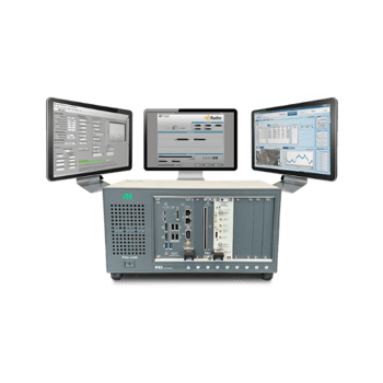
The Averna RP-6500 does both. It is a wideband RF record and playback platform that can record a single 500 MHz channel and it carries a real-time GNSS simulator covering GPS, Galileo, GLONASS, BeiDou, and QZSS. It was built for the field as much as for the bench. The chassis travels in a car trunk, and its software captures the spectrum alongside GNSS location data, so the environment that broke your receiver comes back to the lab and replays as often as the debugging takes. For receivers buried inside an infotainment head unit, where GNSS competes with radio, video, and connectivity traffic in the same enclosure, the AST-1000 all-in-one infotainment signal source covers the same ground.
If you are validating a receiver, an antenna integration, or a full navigation subsystem, get in touch with our team to discuss the test approach that fits your program.
You may also be interested in…
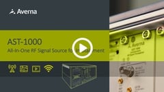
Want to see the all-in-one AST-1000 in action?
Check out this video and see how simple it is to generate worldwide GNSS signals using the AST-1000!


